





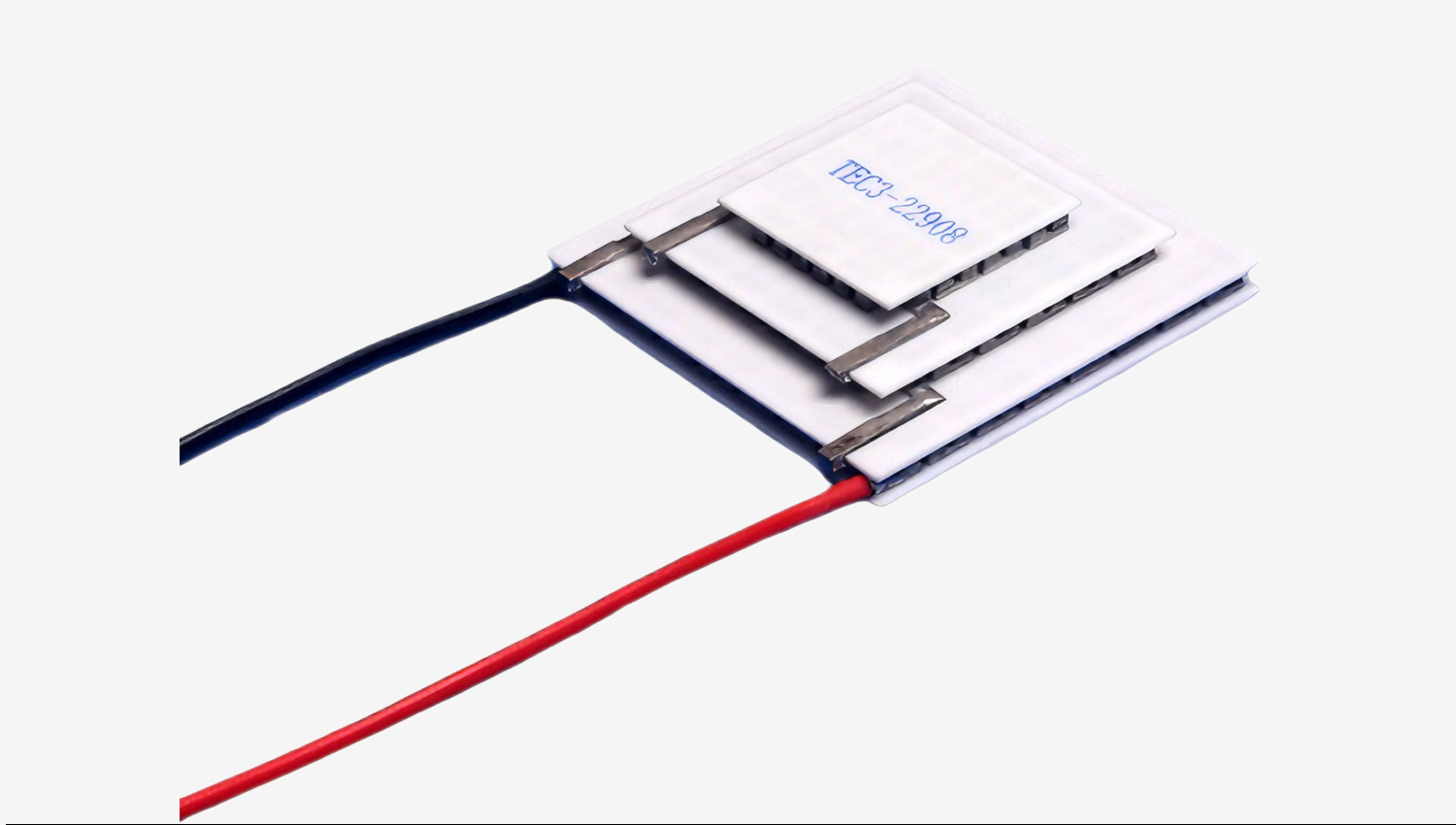
Durable Thermoelectric Cooler: How to Select and Engineer a Long-Lasting TEC Module
A Durable Thermoelectric Cooler is more than just a Peltier module that works well out of the box; it is a component engineered to withstand thermal cycling, moisture, mechanical stress, and continuous operation over an extended lifetime. For engineers and system integrators, selecting a durable TEC means understanding the interplay of materials, operating conditions, and thermal management.
What Makes a Thermoelectric Cooler Durable?
Durability in a thermoelectric cooler depends on several factors: the quality of the bismuth telluride crystals, the robustness of solder joints, the coefficient of thermal expansion (CTE) match between the ceramic plates and the semiconductor pillars, and the effectiveness of moisture barrier coatings. A durable TEC module uses high-purity materials, precision assembly, and rigorous quality testing to ensure that it can handle thousands of thermal cycles without degradation.
In addition to materials, the design of the TEC itself influences reliability. For example, a module designed with a higher number of thermocouples for the same cooling capacity may operate at lower current density, reducing electromigration and prolonging life. Similarly, the choice of ceramic substrate—typically alumina or aluminum nitride—affects both thermal performance and mechanical strength. A durable Peltier cooler is one that is properly matched to its application, so that it operates well within its maximum limits rather than at the edge of failure.
Key Selection Parameters for a Durable Thermoelectric Cooler
When selecting a durable thermoelectric cooler, four key parameters define its performance envelope: Qmax (maximum heat absorption at zero temperature difference), ΔTmax (maximum temperature difference at zero heat load), Imax (current producing ΔTmax), and Vmax (voltage at Imax). It is critical to understand that Qmax and ΔTmax are not achieved simultaneously under the same operating conditions. In practice, a TEC operates anywhere along a curve between these extremes, depending on the heat load and the hot-side temperature.
To ensure durability, avoid operating the TEC at its absolute maximum ratings for extended periods. Running a Peltier module continuously at Imax or above accelerates aging and increases the risk of thermal stress. Instead, select a TEC module that provides the required cooling capacity at 70–80% of its maximum current, leaving a safety margin. This approach not only improves reliability but also reduces power consumption.
Additionally, consider the hot-side temperature. A TEC operates more efficiently and lasts longer when the hot side is kept at a moderate temperature. Excessive hot-side temperatures—often above 80°C—can soften solder interconnects and lead to premature failure. Therefore, a durable thermoelectric cooler system must incorporate adequate heat dissipation to maintain realistic hot-side conditions.
Engineering for Durability: Heat Dissipation and Thermal Management
The most frequent cause of TEC failure is inadequate heat dissipation. A thermoelectric cooler can transfer heat from its cold side to its hot side, but if the hot side cannot reject that heat to the environment, the temperature difference across the module quickly increases, and the TEC may overheat. For a durable system, the hot side must be attached to a heatsink with sufficient thermal capacity and airflow. The thermal resistance of the heatsink is a key parameter: lower thermal resistance means lower hot-side temperature for a given heat load, which directly improves TEC performance and life.
Equally important is the thermal interface material (TIM) between the TEC and the heatsink, and between the TEC and the cold plate. Air gaps are poor thermal conductors; a high-quality TIM—such as thermal grease, phase-change material, or graphite pad—can reduce contact resistance significantly. The TIM must also be compatible with the materials and operating temperatures to avoid pump-out or drying out over time.
Mechanical clamping is another consideration. The TEC is a ceramic structure that can crack if unevenly compressed. Use a uniform pressure across the module, typically between 0.5 and 1.5 MPa, and avoid point loads. A durable thermoelectric cooler installation uses a spring-loaded clamp or a bolted assembly with a compliant layer to accommodate thermal expansion differences between the cold plate and heatsink.
Finally, think about moisture protection. In environments where condensation occurs, a Peltier module can suffer from moisture ingress, leading to corrosion and electrical short circuits. Options include conformal coatings, hermetic sealing, or carefully designed gaskets. A durable thermoelectric cooler for high-humidity applications often incorporates a moisture barrier around the module edges, especially for TEC modules used in portable coolers or sealed enclosures.
Common Causes of TEC Failure and How to Prevent Them
Even the best TEC module can fail prematurely if used incorrectly. Here are common causes of thermoelectric cooler failure and practical prevention strategies.
Thermal cycling stress: Repeated heating and cooling can cause solder joint fatigue. To minimize this, select a TEC with a high solder reflow temperature and design your system to avoid rapid, extreme temperature swings. Also, use a temperature controller with a lower hysteresis to reduce cycling frequency.
Overcurrent/overvoltage: Applying more current than rated causes excess heat inside the module due to Joule heating, degrading the semiconductor material. Always operate within the specified Imax and Vmax, and use a PID controller to regulate current precisely.
Poor heat dissipation: As mentioned earlier, without a proper heatsink, the hot side becomes excessively hot, damaging the TEC. Ensure your heatsink is designed for both the continuous heat load and the maximum ambient temperature.
Moisture ingress: Condensation can corrode internal connections. Apply a conformal coating or use a sealed enclosure, and consider the dew point of the operating environment.
Mechanical damage: Cracks in the ceramic plates often occur due to uneven clamping or impact. Use proper mounting hardware and never apply force directly to the ceramic surface without a compliant pad.
Frequently Asked Questions
Q: How long does a Durable Thermoelectric Cooler typically last?
A: Lifespan depends on operating conditions. A well-designed TEC with proper heat management can run for 100,000 hours or more. However, continuous operation at high current and high hot-side temperature will reduce lifetimes significantly. Always derate from maximum ratings for longest life.
Q: Can a thermoelectric cooler achieve both high Qmax and high ΔTmax simultaneously?
A: No. Qmax occurs when the temperature difference is zero, while ΔTmax occurs when the heat load is zero. Under real operating conditions, the TEC operates somewhere between these extremes. The operating point is determined by the heat load, the hot-side temperature, and the input current.
Q: Is a multi-stage TEC more durable than a single-stage TEC?
A: Multi-stage TECs can achieve higher ΔTmax but are generally more complex and may have lower efficiency. Their durability depends on the same factors—materials, thermal management, and operating conditions. In many cases, a single-stage TEC is preferable if the required ΔT is within its range; simpler design often yields higher reliability.
Q: How do I choose the right TEC for my application?
A: Start by defining the heat load (Qc), the required cold-side temperature (Tc), and the maximum ambient temperature (Tamb). Calculate the required temperature difference (ΔT = Th - Tc), then select a TEC whose ΔTmax is at least 1.5× your required ΔT. Also, ensure the Qmax is roughly 1.5–2× the heat load, and verify that the hot-side heatsink can handle the total power dissipated.
Q: Can I use a thermoelectric cooler for both heating and cooling?
A: Yes, a TEC can work in both modes by reversing the polarity of the current. This makes it useful for temperature stabilization applications. However, durability is improved when the TEC is not toggled rapidly between heating and cooling, as thermal cycling stress can cause fatigue. Use a proper control algorithm to limit switching frequency.
Conclusion
Selecting and engineering a durable thermoelectric cooler requires careful attention to performance parameters, thermal management, mounting, and environmental protection. A TEC module that is properly derated, well dissipated, and securely installed can provide years of reliable service. By understanding the relationship between Qmax, ΔTmax, operating current, and hot-side temperature, you can design a cooling system that not only meets your requirements but also stands the test of time.
META TITLE: Durable Thermoelectric Cooler – Selection and Engineering Guide
META DESCRIPTION: Learn how to select and engineer a durable thermoelectric cooler for long-lasting performance. Understand key TEC parameters, heat dissipation, and reliability best practices.
