




How to Use a Thermoelectric Cooler Recommendation Chart for TEC Selection
How to Use a Thermoelectric Cooler Recommendation Chart for TEC Selection
A Thermoelectric Cooler Recommendation Chart is often the first tool engineers use when narrowing down a Peltier cooler or TEC module. It can quickly show which families of thermoelectric coolers may fit a general cooling range, voltage class, or physical size. However, a chart is not a final design calculation. It is a map of possibilities, and the real selection depends on heat load, hot-side temperature, cold-side temperature, allowable power consumption, and heat dissipation.
What a Thermoelectric Cooler Recommendation Chart Actually Shows
A typical recommendation chart organizes TEC modules by parameters such as cooling capacity, Qmax, ΔTmax, Imax, Vmax, number of stages, and package size. Some charts are simple selection tables. Others include performance curves that show cooling capacity versus temperature difference at a given hot-side temperature and input current.
The chart is most useful when it is treated as a screening tool. It helps you eliminate TEC modules that are clearly too small, too large, too power-hungry, or mechanically unsuitable. It does not replace a detailed thermal calculation because actual thermoelectric cooling performance changes with operating conditions.
Start With Heat Load, Not Qmax
The most common TEC selection mistake is choosing a module based on Qmax alone. Qmax is the maximum heat pumping capacity, but it is specified at ΔT = 0, meaning the hot side and cold side are at the same temperature. In that condition, the TEC moves heat but produces no useful temperature difference. A real application usually needs the cold side to be lower than the hot side, so the available cooling capacity is lower than Qmax.
Begin with the actual heat load. This includes the active load from electronics, sensors, lasers, or samples, plus passive gains through insulation, seals, wiring, and mounting hardware. If the heat load is not known, the TEC may appear to work on paper but fail in the assembled system. For steady-state thermal management, the TEC must remove both the applied heat load and the electrical power that enters through the module.
Understanding Qmax, ΔTmax, Imax, and Vmax
Qmax is the maximum cooling capacity, usually measured at a specified hot-side temperature and maximum current with zero temperature difference. ΔTmax is the maximum temperature difference between the hot side and cold side, usually measured at zero heat load and maximum current. These two values are reference points, not simultaneous operating conditions.
Imax is the current at which Qmax and ΔTmax are typically specified. Vmax is the corresponding maximum voltage at that current and temperature difference. Electrical resistance affects how voltage, current, and power consumption relate to each other. A TEC with a higher Imax and lower voltage may suit a low-voltage supply, while a lower-current, higher-voltage module may be easier to drive with certain controllers.
Qmax and ΔTmax Are Not Simultaneous Operating Points
You cannot normally achieve Qmax and ΔTmax at the same time. Qmax occurs at ΔT = 0. ΔTmax occurs at Q = 0. Real operation lies somewhere between these extremes. As the required temperature difference increases, the cooling capacity decreases. This is why a TEC chart must be read together with the target cold-side temperature and the available hot-side temperature.
Reading the Chart: Cooling Capacity, Current, and Voltage
When reviewing a Thermoelectric Cooler Recommendation Chart, look for the conditions behind the data. A cooling capacity number without a hot-side temperature, current, and ΔT condition is incomplete. For example, a module may provide a certain cooling capacity at ΔT = 20 K, but much less at ΔT = 50 K. The hot-side temperature is equally important because a hotter hot side reduces the achievable temperature difference and cooling capacity.
Voltage and current selection should follow the available power supply and control method. If the system uses a fixed voltage, the TEC may not operate at its rated current unless a controller or resistor network is used. If the system uses current control, the voltage will vary with temperature and heat load. In either case, the chart should be used to compare candidate modules under the same assumed operating conditions, not under unrelated datasheet extremes.
Heat Dissipation and Hot-Side Temperature: The Hidden Limiter
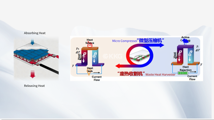
A TEC moves heat from the cold side to the hot side, but that heat must then leave the hot side through a heatsink, cold plate, fan, or liquid loop. If heat dissipation is poor, the hot side rises, ΔT shrinks, and the cold side cannot reach the target temperature. In many failed Peltier cooler designs, the TEC is not the main problem. The thermal path from the hot side to ambient is.
Pay close attention to heatsink performance, thermal resistance, thermal interface material, mounting pressure, and ambient temperature. A low thermal resistance path from the TEC hot side to the final heat sink is essential. The cold side also needs a controlled thermal path to the object being cooled. Air gaps, uneven mounting, and poor interface materials add thermal resistance and reduce real cooling capacity.
Matching a TEC Module to Real Operating Conditions
Use the chart to shortlist TEC modules, then calculate the actual design point. The design point should include heat load, target cold-side temperature, expected hot-side temperature, ambient temperature, available voltage, available current, allowable power consumption, and mechanical limits. After that, compare candidate modules using performance curves or supplier selection tools that allow the hot-side temperature and input current to be adjusted.
For applications requiring a large temperature difference, a multi-stage TEC may be appropriate. For compact optical sensors or small medical devices, a miniature TEC may fit better. For high ambient or high-temperature environments, a high-temperature TEC may be needed. When standard modules do not match the mechanical or thermal requirement, a custom TEC can be designed around the application. KKG supports standard and custom thermoelectric cooling categories, but the final selection should always be based on measured or calculated system conditions.
Practical Selection Workflow
Step 1: Define the heat load and target cold-side temperature. Step 2: Estimate the hot-side temperature from the heatsink and ambient conditions. Step 3: Calculate the required ΔT. Step 4: Use the Thermoelectric Cooler Recommendation Chart to shortlist modules with suitable Qmax, Imax, Vmax, and size. Step 5: Verify performance at the real hot-side temperature and input current. Step 6: Confirm heat dissipation, power consumption, and control limits.
Application Examples and Engineering Considerations
In a small enclosure cooling application, the TEC must handle both the internal heat load and heat leaking through insulation. The hot side may be cooled by a forced-air heatsink. If the ambient temperature is high, the achievable ΔT may be much lower than the datasheet ΔTmax. In that case, increasing heatsink performance or reducing heat load may be more effective than choosing a larger TEC.
In precision temperature control, the TEC may operate in both heating and cooling modes. The controller must manage current direction, temperature feedback, and thermal lag. In semiconductor cooling for lasers or detectors, stable cold-side temperature and low thermal resistance are often more important than maximum cooling capacity. These applications show why a recommendation chart is a starting point, not a complete design solution.
Frequently Asked Questions
Can I select a TEC using Qmax alone?
No. Qmax is measured at ΔT = 0 and does not represent useful cooling under a real temperature difference. You also need the heat load, target ΔT, hot-side temperature, and available current. A module with a high Qmax may still fail if the heatsink cannot keep the hot side cool enough.
Why does my TEC not reach the ΔTmax shown on the chart?
ΔTmax is specified at zero heat load and a specific hot-side temperature. Any real heat load reduces the achievable temperature difference. Poor heat dissipation, high ambient temperature, thermal interface losses, and insufficient current can also prevent the system from reaching the datasheet value.
Should I choose a higher-current or higher-voltage TEC?
It depends on the power supply, controller, and thermal design. A higher-current module may require thicker wiring and a driver with higher current capability. A higher-voltage module may be easier to drive with certain supplies, but the actual operating voltage still depends on current and temperature. Compare modules at the same ΔT and hot-side temperature.
How much heat sink do I need for a Peltier cooler?
The heatsink must remove the TEC input power plus the heat load. Its thermal resistance, airflow, mounting method, and ambient temperature determine the hot-side temperature. If hot-side temperature rises, cooling capacity falls. In many systems, improving the heatsink is more effective than increasing TEC size.
When should I consider a multi-stage or custom TEC?
A multi-stage TEC may be useful when a single-stage module cannot achieve the required ΔT. A custom TEC may be appropriate when standard dimensions, voltage, current, or thermal paths do not fit the application. The decision should follow a thermal calculation, not a chart alone.
Conclusion
A Thermoelectric Cooler Recommendation Chart is a useful first step in TEC selection because it narrows the field of Peltier modules by cooling capacity, size, voltage, current, and stage count. However, the final choice must be based on real operating conditions: heat load, hot-side temperature, cold-side temperature, ΔT, heat dissipation, thermal resistance, and power consumption. Qmax and ΔTmax are reference values, not simultaneous operating points. By using the chart as a screening tool and then verifying performance with a proper thermal calculation, engineers can design more reliable thermoelectric cooling systems and avoid the common problem of a TEC that performs well on paper but poorly in the real assembly.
Meta Information
META TITLE: TEC Selection: Thermoelectric Cooler Recommendation Chart
META DESCRIPTION: Learn how to read a Thermoelectric Cooler Recommendation Chart, match Qmax, ΔTmax, heat load, and heat dissipation, then select a TEC module for reliable cooling.
