


Shenzhen Thermoelectric Cooler Selection Guide: Qmax, ΔTmax, and Thermal Design
Shenzhen Thermoelectric Cooler Selection Guide: Qmax, ΔTmax, and Thermal Design
Specifying a Shenzhen Thermoelectric Cooler is not simply a matter of choosing a Peltier module with the highest cooling capacity. A thermoelectric cooler is a heat pump that must be matched to the application’s heat load, required temperature difference, available power, ambient conditions, and heat-sink performance. Engineers evaluating a TEC module from Shenzhen should treat the datasheet as a starting point, then verify the actual operating point in the system.
This article explains how to read key TEC parameters such as Qmax, ΔTmax, Imax, and Vmax, and how to relate them to cooling capacity, power consumption, thermal resistance, and thermal management. It is written for design engineers, product teams, and technical buyers who need a practical selection method rather than a product ranking.
What a Shenzhen Thermoelectric Cooler Means in an Engineering Specification
In procurement and engineering discussions, “Shenzhen Thermoelectric Cooler” usually refers to a thermoelectric cooler module sourced from a Shenzhen-based manufacturer or supplier. The location itself is not a performance specification. The important factors are the TEC module’s thermoelectric material, mechanical construction, dimensional tolerance, electrical characteristics, and documented test conditions.
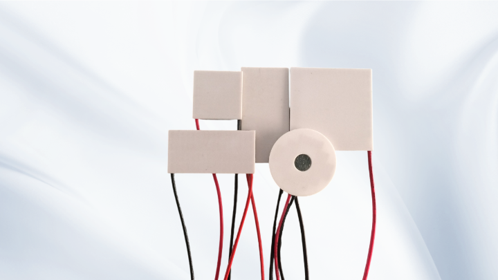
A Peltier cooler and a TEC module refer to the same basic device: an array of semiconductor pellets that moves heat when current flows through it. One side becomes the cold side and the other becomes the hot side. Reversing the current reverses the heat-pumping direction. Because the device is solid state, it can be small, quiet, and precise, but it still requires proper heat dissipation on the hot side.
When comparing a Shenzhen Thermoelectric Cooler for a design, ask for consistent datasheet conditions. The most useful data include cooling capacity versus current, temperature difference versus current, voltage versus current, and performance at the intended hot-side temperature. Without this information, a single Qmax number can be misleading.
Start With the Heat Load, Not the Module
The first step in TEC selection is to define the heat load. This includes active heat generated by electronics, passive heat entering through insulation, thermal bridges, convection, radiation, and any heat absorbed from the environment. For a small enclosure, the passive load can be significant and is often underestimated.
Define the required cold-side temperature and the expected hot-side temperature. The difference between them is the operating temperature difference, not the datasheet ΔTmax. The cooling capacity of the TEC must be greater than the total heat load at that real temperature difference, with margin for tolerances and aging.
Also define the ambient temperature, duty cycle, warm-up conditions, and whether condensation is possible. These factors influence insulation, sealing, control strategy, and thermal interface material selection. A TEC that works in a laboratory at room temperature may behave differently in a warm enclosure or at a low cold-side setpoint.
Reading Qmax, ΔTmax, Imax, and Vmax Correctly
Qmax is the maximum heat-pumping capacity, normally specified when the temperature difference between the cold side and hot side is zero. ΔTmax is the maximum temperature difference the module can develop, normally specified when the heat load is zero. These are boundary conditions, not normal operating conditions.
This point is critical: Qmax and ΔTmax cannot normally be achieved at the same time under the same operating condition. If a TEC is pumping its maximum heat load, the temperature difference is near zero. If it is producing its maximum temperature difference, the useful cooling capacity is near zero. Real operation lies somewhere between these limits.
Imax and Vmax describe electrical limits at specified test conditions. They do not mean the module should always be driven at those values. In many systems, the best operating point is below Imax to reduce power consumption, improve efficiency, and limit heat rejection. The applied voltage and current limit, together with the module’s electrical resistance, determine the actual operating point.
A datasheet may also list AC resistance or electrical resistance. This value helps estimate voltage drop and power consumption, but it changes with temperature. For engineering design, use the manufacturer’s performance curves and verify the selected operating point with a prototype.
Hot-Side Temperature and Heat Dissipation Drive Real Performance
The hot side of a thermoelectric cooler is where the heat load plus the TEC’s input power must be removed. If heat dissipation is inadequate, the hot-side temperature rises, the achievable temperature difference falls, and the cooling capacity drops. In severe cases, the TEC can overheat or fail.
Heat-sink performance is described by thermal resistance. A lower thermal resistance from the TEC hot side to ambient helps maintain a lower hot-side temperature. The thermal path includes the TEC ceramic surface, thermal interface material, heat sink base, heat sink fins, airflow, and ambient conditions. Each interface adds thermal resistance.
Thermal interface material must be thin, consistent, and appropriate for the temperature range. Dry mounting or poor surface flatness can create hot spots. Forced-air heat sinks, liquid cooling, or heat pipes may be required depending on power density. The heat sink must remove heat load plus input power, not just the cooling load.
Matching Voltage and Current to the Available Power Supply
Voltage and current selection should follow the thermal requirement. A common mistake is to choose a TEC module based only on a convenient voltage, then discover that the current limit is too low to reach the required cooling capacity. Another mistake is to drive a module at Imax continuously without evaluating power consumption and heat rejection.
For battery-powered or portable systems, power consumption matters as much as cooling capacity. A smaller TEC module operated efficiently may be better than a larger module driven at high current. For precision temperature control, choose a driver with low ripple and stable current control. Unfiltered PWM can create electrical noise and thermal cycling, so filtering or linear control may be preferable in sensitive applications.
Consider startup conditions and maximum ambient temperature. The TEC may draw more current when the temperature difference is high. The power supply, wiring, connectors, and controller should be rated for the worst-case electrical load, not only the nominal operating point.
Practical Selection Workflow for a Shenzhen Thermoelectric Cooler
A practical workflow helps avoid oversized modules, insufficient heat sinks, and late-stage redesign. The following sequence works for many thermoelectric cooling projects:
1. Define the thermal requirement. Specify heat load, cold-side target, hot-side limit, ambient temperature, duty cycle, and allowable power consumption.
2. Estimate the operating temperature difference. Use the expected hot-side temperature, not a laboratory value, and include margin for real-world heat dissipation.
3. Review TEC performance curves. Select a Peltier module that can provide the required cooling capacity at the required temperature difference, not just at Qmax.
4. Select the heat-dissipation method. Calculate the total heat to be removed and choose a heat sink with sufficient thermal resistance for the ambient and airflow conditions.
5. Check the electrical operating point. Confirm voltage, current, power consumption, and controller capability at the expected hot-side and cold-side temperatures.
6. Prototype and measure. Validate temperature difference, cooling capacity, power draw, condensation risk, and control stability in the actual enclosure.
For product categories, a miniature TEC may suit small sensors or optical components, a high-temperature TEC may be relevant when the hot side runs warm, a multi-stage TEC may be considered for a larger temperature difference, and a custom TEC may be needed for unusual dimensions or mounting. KKG supplies these TEC categories, and the same engineering checks apply regardless of module type.
Application Scenarios and Design Notes
In electronics enclosures, a thermoelectric cooler can maintain a component below ambient, but the enclosure must be insulated and sealed to reduce passive heat gain. The hot-side heat sink may need to be outside the cooled space. Condensation control is important when the cold side drops below the dew point.
For laser diodes and optical sensors, temperature stability may matter more than raw cooling capacity. A smaller TEC module with a well-tuned controller can provide stable temperature, while a larger module may introduce unnecessary power consumption and thermal stress.
In medical or laboratory equipment, multi-stage TEC assemblies may be used when a large temperature difference is required. However, multi-stage modules are less efficient and require careful heat rejection. Each stage adds complexity, so the design should be justified by the thermal target.
Common Engineering Mistakes to Avoid
Treating Qmax as usable cooling capacity is one of the most common errors. Always evaluate cooling capacity at the real temperature difference. Another common issue is undersizing the heat sink or ignoring the TEC’s own power dissipation.
Poor thermal interface material, uneven mounting pressure, and contaminated surfaces increase thermal resistance. Lack of insulation around a cooled enclosure allows moisture and heat to enter. Driving a TEC with unfiltered PWM can cause noise and thermal cycling. Finally, testing only at room temperature can hide problems that appear at high ambient or low setpoint.
Frequently Asked Questions
How do I choose between Qmax and ΔTmax when selecting a TEC?
Do not choose based on either value alone. Use the performance curve at your expected hot-side temperature and identify the operating point that provides enough cooling capacity at your required temperature difference. Qmax is a boundary value at zero temperature difference, while ΔTmax is a boundary value at zero heat load.
Can I operate a Shenzhen Thermoelectric Cooler at Imax continuously?
It may be electrically possible, but it is often not the best thermal or efficiency choice. Continuous operation at Imax increases power consumption and heat rejection. Select the current that meets the cooling requirement with acceptable margin and verify the hot-side temperature.
Why does my TEC fail to reach the expected temperature?
Check heat-sink performance, thermal interface material, insulation, heat load, and ambient temperature. A rising hot-side temperature reduces cooling capacity. Also confirm that the power supply can deliver the required current at the actual operating voltage.
What information should I provide to a TEC manufacturer?
Provide heat load, target cold-side temperature, expected hot-side temperature, ambient conditions, available voltage and current, allowable power consumption, size constraints, and duty cycle. These details allow a more meaningful TEC recommendation than a single temperature target.
Conclusion
Selecting a Shenzhen Thermoelectric Cooler is a thermal-design exercise, not a catalog lookup. Qmax, ΔTmax, Imax, and Vmax are useful boundaries, but actual performance depends on heat load, hot-side temperature, cold-side temperature, voltage, current, heat-sink thermal resistance, interface materials, and installation conditions.
By defining the real thermal load, evaluating performance at the expected operating point, and designing robust heat dissipation, engineers can use thermoelectric cooling effectively. Whether the project requires a miniature TEC, a high-temperature TEC, a multi-stage TEC, or a custom TEC module, the same disciplined selection process helps ensure reliable thermal management.
Meta Title
Shenzhen Thermoelectric Cooler Selection Guide: Qmax and ΔTmax
Meta Description
Learn how to select a Shenzhen Thermoelectric Cooler by matching heat load, Qmax, ΔTmax, voltage, current, and hot-side heat dissipation.