




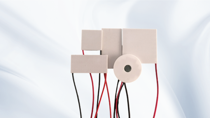
Thermoelectric Cooler Factory: A Technical Guide to TEC Selection, Design and Manufacturing
Why Your Thermoelectric Cooler Factory Choice Shapes the Whole Design
Selecting a Thermoelectric Cooler Factory is not only a purchasing decision. A Peltier cooler is a precision assembly of semiconductor pellets, ceramic substrates, solder joints and sealing materials, and small differences in any of those elements change the electrical and thermal behaviour of the finished TEC module. The factory's process control therefore becomes part of your thermal design margin.
A genuine thermoelectric cooler manufacturer controls pellet sorting, substrate selection, solder alloy choice, reflow profiles, curing and end-of-line testing. A trading company that resells modules may offer competitive prices, but it usually cannot tell you why one batch of TEC modules draws more current than the previous one, or why a module that passed bench testing fails after thermal cycling in the field.
When you understand what a factory actually controls, you can ask better questions during sourcing — and you get a product that behaves predictably across production batches, not just in the first prototype.
Core Parameters a Thermoelectric Cooler Factory Should Help You Interpret
Every TEC datasheet lists a small set of parameters: Qmax, ΔTmax, Imax, Vmax and AC resistance. These values are reference points measured under defined conditions, normally with the hot side held at a fixed reference temperature and the module in a vacuum or well-insulated fixture.
Qmax is the maximum cooling capacity, and it is reached only when the temperature difference between the hot side and the cold side is zero — in other words, when the module is pumping heat but producing no useful cooling effect. ΔTmax is the maximum temperature difference, and it occurs only at zero heat load, with no thermal energy being pumped at all.
This is the single most misunderstood point in thermoelectric cooling: Qmax and ΔTmax cannot be achieved at the same time under the same operating conditions. In a real system you operate somewhere on the performance curve between those two extremes, and the actual cooling capacity at your required temperature difference is always lower than Qmax.
Imax is the current at which Qmax and ΔTmax are specified, and Vmax is the corresponding voltage at that current. Driving a module beyond Imax increases Joule heating faster than it increases cooling, so the module can actually get worse. AC resistance, usually measured at around 1 kHz, is a fast indicator of joint quality and batch consistency.
A capable thermoelectric cooler manufacturer will not simply send you a datasheet. It will explain how those reference values shift when your hot-side temperature, input voltage or heat load differs from the test conditions.
Selecting a TEC Module for Real Operating Conditions
Real-world selection starts from the application, not from the catalogue. The practical sequence is to define the heat load, the required cold-side temperature, the available hot-side temperature, and the acceptable power consumption — then find a module that delivers the required cooling capacity within those limits.
A useful mental model is that the module must pump the heat load plus the electrical power it consumes, and all of that energy must leave through the hot side. If the heat sink cannot remove it, the hot-side temperature rises, the achievable temperature difference shrinks, and the cooling capacity falls. This is why oversizing a TEC rarely solves a thermal problem — it often makes it worse by adding more waste heat.
Practical points worth checking before committing to a design:
• Confirm the module's rated conditions match your hot-side temperature range, not just room temperature.
• Derate the expected cooling capacity rather than assuming Qmax is available.
• Check power consumption and coefficient of performance, especially for battery-powered or sealed products.
• Ask how the module behaves at reduced voltage, which is often used to lower current draw.
For miniature or space-constrained designs, small-footprint Peltier modules and thin-profile TEC categories are usually the right starting point, while high-power applications generally need larger pellets and higher thermal conductivity substrates.
Heat Dissipation and Thermal Management: Where Most TEC Designs Fail
Thermoelectric cooling does not destroy heat — it moves it. That means the hot side of the module is always the critical interface, and heat dissipation determines whether the design works.
The thermal path from the cold-side load to the ambient air includes several resistances in series: the load interface, the module itself, the hot-side interface, the heat sink base, and the heat sink to air. Total thermal resistance sets the hot-side temperature rise above ambient for a given total heat flow. Reducing any single resistance has a direct effect on achievable cooling.
In practice, the most common failure points are:
• Insufficient heat sink performance or airflow for the combined heat load plus input power.
• Poor thermal interface material application, or use of a material that degrades over thermal cycling.
• Uneven mounting pressure, which bends the ceramic substrate and creates internal stress.
• Condensation on the cold side when the surface drops below dew point, leading to corrosion or electrical leakage.
A thermoelectric cooler manufacturer can usually advise on mounting torque, interface materials and sealing options, but the heat sink and airflow design remain the system integrator's responsibility — and they are the deciding factor in most projects.
Custom, Multi-Stage, Miniature and High-Temperature TEC Options
Standard catalogues cover a wide range, but many applications need something specific. Custom TEC development typically adjusts pellet geometry, pellet count, substrate material and solder alloy to match a target voltage, current, footprint or temperature range.
Multi-stage TEC designs stack modules to reach larger temperature differences than a single stage can provide. Single-stage bismuth telluride modules generally reach a ΔTmax in the range of roughly 65 to 70 K under reference conditions, while cascaded stages can extend that further — at the cost of significantly lower efficiency and higher power consumption. Multi-stage modules should be chosen when the temperature difference requirement is genuinely large, not as a general upgrade.
High-temperature TEC modules use solder alloys and substrate constructions that tolerate elevated hot-side conditions, which matters in industrial, automotive and instrumentation environments. Miniature TEC modules serve optical, medical and compact sensor applications where footprint matters more than raw cooling capacity.
It is worth describing your operating envelope to the factory early: hot-side temperature, cold-side target, heat load, duty cycle, ambient conditions and mechanical constraints. These inputs usually determine which construction is realistic.
Quality Control and What to Ask Before You Commit
Consistency is what separates a reliable supplier from a low-cost one. A thermoelectric cooler factory that tests every module for AC resistance, dimension, appearance and, where relevant, cooling performance gives you traceable data rather than a promise.
Questions worth asking during qualification:
• How is AC resistance measured, and what is the batch tolerance?
• Are modules thermally cycled or burn-in tested before shipment?
• What solder alloy and sealing method are used, and for which temperature range?
• Can the factory supply dimensional drawings and material declarations?
• How are deviations handled if a batch falls outside specification?
Answers to these questions tell you more about long-term reliability than any single performance figure on a datasheet.
Frequently Asked Questions
Can a TEC module deliver Qmax and ΔTmax at the same time?
No. Qmax is defined at zero temperature difference and ΔTmax at zero heat load. Any real operating point sits between them, and the usable cooling capacity at your required temperature difference is always lower than Qmax. Design margins should be based on the actual operating point, not on the headline figures.
Should I choose a single-stage or a multi-stage TEC?
Choose multi-stage only when the required temperature difference cannot be reached with a single stage under your hot-side conditions. Multi-stage modules add cost, complexity and power consumption, and they are less efficient for the same cooling capacity. If a single stage plus a better heat sink can meet the target, that is usually the more practical route.
What information does a thermoelectric cooler factory need for a quotation?
Provide the heat load, target cold-side temperature, expected hot-side temperature or heat sink capability, ambient conditions, available voltage and current, footprint limits, duty cycle and any mechanical or sealing requirements. With those inputs, a factory can recommend an existing module or propose a custom design instead of guessing.
Why does my Peltier cooler perform worse in the product than on the bench?
The most common causes are inadequate hot-side heat dissipation, poor thermal interface contact, air trapped between surfaces, and heat leaking back through the module or surrounding insulation. The module itself is often working correctly — the surrounding thermal system is not removing the pumped heat efficiently enough.
How much does input voltage affect cooling performance?
Cooling capacity rises with current up to a point, then falls as Joule heating dominates. Operating below Imax reduces power consumption and can improve efficiency, but it also reduces the achievable temperature difference. Voltage and current should be selected together with the required heat load in mind, not treated as independent settings.
Conclusion
Working effectively with a Thermoelectric Cooler Factory comes down to understanding the physics behind the datasheet. Qmax and ΔTmax are reference points measured under specific conditions and cannot be achieved simultaneously; real performance depends on heat load, hot-side temperature, input current, heat sink quality and thermal interfaces.
The factory side of the equation is process control, material selection, testing and the ability to explain how a module behaves outside its reference conditions. The system side is heat dissipation, mechanical mounting and condensation management. When both are handled properly, thermoelectric cooling delivers precise, compact and reliable temperature control — but the module must be selected for the actual operating point, not for the marketing numbers on a specification sheet.
