


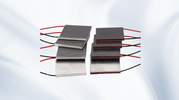
Thermoelectric Cooler Strong Manufacturer: An Engineering Guide to TEC Selection and Integration
A Thermoelectric Cooler Strong Manufacturer is not defined by a catalog page alone. It is defined by how clearly the supplier connects module specifications to the thermal, electrical, and mechanical realities of an application. A Peltier cooler can look simple—apply voltage, create a temperature difference—but real performance depends on heat load, hot-side temperature, cold-side temperature, heatsink performance, and installation quality. This guide explains the engineering points to check when selecting TEC modules and working with a capable thermoelectric cooling supplier.
Start With the Application, Not the Module
Before comparing any Peltier module, define the thermal problem. What is being cooled? What is the heat load in watts? What cold-side temperature is required? What hot-side temperature or ambient temperature is available? How much space is allowed? What power supply voltage and current limits exist? These questions matter more than a headline cooling capacity number because a thermoelectric cooler only performs well inside a complete thermal design.
Two systems can use the same TEC module and perform very differently because one has a well-designed heatsink and the other does not. For that reason, TEC selection should begin with a thermal budget and end with a verified assembly design. A useful first step is to separate the required cooling duty from the heat that the module itself will generate. The hot side must reject both the heat removed from the cold side and the electrical power consumed by the module.
What a Thermoelectric Cooler Strong Manufacturer Should Provide
A capable manufacturer should support more than module shipment. It should provide understandable datasheets, application notes, and engineering guidance on how to read performance curves. The supplier should clearly state the test conditions for parameters such as Qmax, ΔTmax, Imax, Vmax, and electrical resistance. It should also explain that these values are reference points, not guarantees that every parameter can be achieved at the same time in a real assembly.
Good technical support also means asking the right questions about heat load, ambient conditions, control method, mounting orientation, and available power. For design teams, KKG’s TEC product categories include miniature, high-temperature, multi-stage, and custom thermoelectric cooling options, but the final choice should always follow the thermal and electrical requirements rather than the other way around.
Reading Qmax, ΔTmax, Imax, and Vmax Correctly
Qmax is the maximum cooling capacity at a specified condition, usually when the temperature difference is zero and the module is driven at Imax. ΔTmax is the maximum temperature difference, usually at zero heat load. Imax and Vmax define maximum current and voltage conditions. These parameters are useful for comparing module families, but they should not be treated as simultaneous operating points.
In practice, cooling capacity decreases as the temperature difference increases. A module may provide high cooling capacity at a small ΔT, or a large ΔT at a small heat load, but it cannot normally deliver Qmax and ΔTmax together under the same operating condition. Actual performance also depends on hot-side temperature, cold-side temperature, input voltage, input current, heatsink performance, thermal interface material, installation pressure, and ambient temperature. The input power is not converted entirely into cooling; Joule heating and other losses increase the heat that must be removed from the hot side.
Heat Dissipation and Thermal Resistance Decide Real Performance
The hot side is often the limiting side of a thermoelectric cooling system. Every watt removed from the cold side plus the electrical input power must leave through the heatsink. If the heatsink, fan, thermal interface, or airflow path has high thermal resistance, the hot side will rise. A higher hot-side temperature reduces the achievable temperature difference and can also reduce cooling capacity at the cold side.
The cold-side thermal path matters as well. Poor contact between the TEC module and the object being cooled adds thermal resistance, while insufficient insulation allows ambient heat to leak into the cold assembly. Mounting pressure, surface flatness, and the choice of thermal interface material are small details that can have a large effect on final performance. For reliable thermal management, design the heatsink and cold-side path together with the TEC module rather than treating them as separate parts.
A Practical Selection Workflow
Step 1: Define the heat load. Include the active load, passive heat leaks, and any transient peaks. If the load is not known, estimate it from the thermal mass, target pull-down time, and insulation quality.
Step 2: Set the temperature targets. Record the required cold-side temperature, expected hot-side temperature, and maximum ambient temperature. The difference between cold side and hot side is the ΔT the module must work against.
Step 3: Choose a module family. Compare TEC modules using performance curves at the expected hot-side temperature, not only at the standard reference condition. Check whether the required cooling capacity is available at the required ΔT.
Step 4: Check voltage and current limits. Match the module to the available power supply and control electronics. Operating below Imax can improve efficiency and reduce thermal stress, while operating above rated conditions is not an acceptable design strategy.
Step 5: Design heat dissipation. Select a heatsink and fan combination with enough capacity for the total heat rejected at the hot side. Account for thermal resistance from the module to the heatsink, from the heatsink to air, and from the cold side to the load.
Step 6: Build and test a prototype. Measure temperatures, input power, and pull-down behavior under realistic ambient conditions. A design that works on a bench with free airflow may fail inside an enclosure.
Custom and Specialized TEC Options
Miniature TEC modules can be useful in compact optical, sensor, or electronics cooling applications where space is limited. High-temperature TEC modules may be relevant when the hot-side environment is unusually warm, but the entire assembly must still be evaluated for thermal stress and control stability. Multi-stage TEC modules can support larger temperature differences, but they usually trade cooling capacity, efficiency, and cost, so they should be selected only when a single-stage module cannot meet the requirement.
Custom TEC assemblies may include specific ceramic dimensions, lead configurations, sealing, or mechanical integration. A Thermoelectric Cooler Strong Manufacturer should explain these trade-offs clearly instead of promoting a module for every case. The goal is a matching solution, not the most complex one.
Frequently Asked Questions
Can a TEC reach Qmax and ΔTmax at the same time?
No. Qmax is normally specified at zero temperature difference, while ΔTmax is normally specified at zero heat load. In a real application, the module operates somewhere between these conditions, depending on heat load, hot-side temperature, cold-side temperature, and input power.
Why does my Peltier cooler fail to reach the target cold-side temperature?
Common causes include an underestimated heat load, poor hot-side heat dissipation, high thermal resistance at the module interfaces, insufficient insulation around the cold side, or operation outside the intended voltage and current range. Check the hot-side temperature first, because a rising hot side quickly reduces achievable ΔT.
What information should I provide for custom TEC selection?
Provide the heat load, target cold-side temperature, expected hot-side temperature, ambient conditions, available voltage and current, allowable size, mounting constraints, control method, and expected duty cycle. These details allow an engineer to evaluate cooling capacity at realistic operating conditions rather than only comparing catalog maximums.
Does a higher Imax or Vmax always mean better cooling?
No. Higher current and voltage ratings may indicate a larger module, but they also increase power consumption and heat rejection. The correct choice depends on the required cooling capacity at the required temperature difference, plus the ability of the heatsink and power supply to support that operating point.
How do I evaluate a Thermoelectric Cooler Strong Manufacturer?
Look for clear datasheets, realistic performance curves, engineering support, consistent quality processes, and a willingness to discuss thermal resistance, heat dissipation, and application limits. A strong supplier should help you understand why a module fits the design, not simply quote a Qmax value.
Conclusion
Selecting a TEC is a thermal engineering task. Qmax, ΔTmax, Imax, Vmax, heat load, heat dissipation, and thermal resistance must be evaluated together, and actual performance must be confirmed at the expected hot-side and cold-side temperatures. A Thermoelectric Cooler Strong Manufacturer helps by providing transparent specifications, practical engineering guidance, and suitable module options for the application. The best result comes from matching the thermoelectric cooler to the full thermal system, not from choosing the largest module on the page.
SEO Meta Information
Meta Title: Thermoelectric Cooler Strong Manufacturer: TEC Guide
Meta Description: Learn how to evaluate a Thermoelectric Cooler Strong Manufacturer, read Qmax and ΔTmax, manage heat load and thermal resistance, and select reliable TEC modules.