


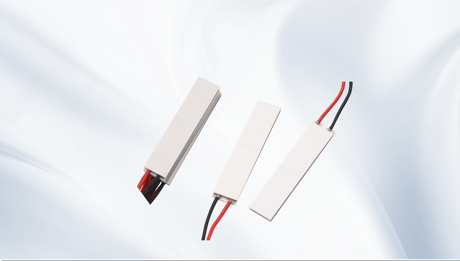
Thermoelectric Cooler Top 10 Brands: A Practical TEC Selection Guide for Engineers
Why the Thermoelectric Cooler Top 10 Brands Mindset Can Mislead You
Most engineers searching for the thermoelectric cooler top 10 brands are not looking for a popularity contest. They are trying to build a shortlist of suppliers whose Peltier modules can meet a defined heat load, a defined temperature difference, and a defined footprint inside a real enclosure. A brand name alone answers none of those questions.
What matters far more is whether a supplier publishes complete, self-consistent datasheets and can explain how a module behaves when the hot side is not held at a laboratory condition. This guide is written from the perspective of a TEC manufacturer and application engineer. Rather than ranking companies, it explains how to judge the technical substance behind any brand on your list, and how to select a module that performs in production.
Read the Datasheet Before You Trust the Logo
A trustworthy thermoelectric cooler datasheet defines its parameters under clearly stated conditions, usually a fixed hot-side temperature. If a supplier cannot tell you at what hot-side temperature the curves were measured, the numbers are not usable for design work.
Qmax: Maximum Cooling, but Only at Zero ΔT
Qmax is the maximum heat pumping rate of the module. It is defined at ΔT = 0 — that is, with no temperature difference between the cold side and the hot side — while driven at Imax and the corresponding Vmax for the stated hot-side temperature. In any real application there is always a temperature difference, so the usable cooling capacity is always lower than Qmax.
ΔTmax: Maximum Temperature Difference, but Only at Zero Load
ΔTmax is reached when the module pumps no useful heat load at all (Qc = 0). This is the opposite extreme from Qmax. Because of that, Qmax and ΔTmax can never be achieved at the same time under the same operating condition. Treating them as simultaneous specifications is one of the most common mistakes in Peltier cooler selection.
Between those two extremes sits a performance curve. Your actual operating point lies somewhere on that curve, determined by your heat load and the hot-side temperature you can realistically maintain.
Imax, Vmax and AC Resistance
Imax and Vmax are the current and voltage at which the reference parameters are defined. They are not necessarily the best operating point. Driving a module above Imax increases Joule heating faster than it increases cooling, so performance can actually fall while power consumption rises. AC resistance matters as well when you match the module to a controller, since it defines the drive voltage needed at your target current and influences resistive losses and driver selection.
From Parameters to a Real Selection Workflow
Selection is a sequence of small decisions, and each one constrains the next.
Step 1 — Define the total heat load. Include the active load plus parasitic gains: conduction through mounts, radiation, convection from the cold-side surface, and heat carried by wires. Parasitic gains are frequently underestimated and can dominate in small systems.
Step 2 — Set the cold-side and hot-side temperatures. Your cold-side target is fixed by the application. The hot-side temperature is fixed by your heat dissipation path, not by preference. Always design for the hot-side temperature the heatsink can hold in the worst-case ambient.
Step 3 — Calculate the required ΔT as hot side minus cold side at that worst-case condition, and keep a practical engineering margin below the module ΔTmax rating, since COP falls sharply as you approach the limit.
Step 4 — Interpolate the datasheet curves at your required ΔT and hot-side temperature to read the achievable Qc, the input current, and the input voltage at that point. Confirm Qc exceeds your total heat load.
Step 5 — Size the heatsink for the total rejected heat, which is roughly the pumped heat plus the electrical input power. The heatsink and fan must remove this sum, not just the cooling capacity.
Why Hot-Side Thermal Management Decides the Result
The hot side is where most thermoelectric cooling projects fail. Because ΔT is measured between the ceramic faces of the module, every additional degree of hot-side temperature directly reduces cold-side performance — often by a larger amount than expected.
Key factors include heatsink thermal resistance, airflow, mounting pressure and surface flatness, and the thermal interface material between the module and both the load and the heatsink. A thin, controlled bond line of the correct interface material is far better than a thick layer. Uneven clamping forces bend the ceramics and create local hot spots that degrade the module over time.
Condensation is the other design constraint: whenever the cold side drops below the local dew point, moisture control, sealing, and conformal coating become part of the thermal design, not an afterthought.
Matching Module Type to the Application
Different applications call for different TEC architectures, and this is where a supplier's real engineering capability shows.
Single-stage modules cover the majority of cooling and temperature-stabilization tasks and offer the best efficiency for a given heat load. They are the default choice for enclosure cooling, sample holders, and sensor stabilization.
Multi-stage modules stack stages to reach larger temperature differences, but the achievable heat load at those extremes is small and power consumption is high. They suit detector, optical, and scientific applications where deep cooling matters more than efficiency.
Miniature and micro TEC modules serve laser diodes, photonics, sensors, and lab-on-chip platforms, where footprint and mass dominate. Their small size makes thermal interfacing even more critical, since parasitic gains scale poorly with shrinking geometry.
High-temperature TEC modules use materials and joining processes that tolerate elevated hot-side temperatures, making them suitable for automotive, industrial, and outdoor equipment where the ambient or the heat sink runs hot.
Custom TEC modules allow footprint, leg geometry, lead configuration, sealing, and surface finish to be adapted to the mechanical design instead of forcing the design around a catalog part.
How to Use a Thermoelectric Cooler Top 10 Brands Shortlist Properly
Once you have a list of candidate suppliers, evaluate them on engineering evidence rather than marketing claims.
Ask whether the datasheet includes performance curves at more than one hot-side temperature, whether AC resistance and dimensional tolerances are specified, and whether the supplier can provide thermal cycling or reliability data for the intended duty cycle. Check whether technical support comes from application engineers who can discuss ΔT, Qmax derating, and heatsink sizing — or only from a sales desk.
Also confirm the practical points: consistent lot-to-lot performance, solder and sealing options for your environment, RoHS and REACH compliance, realistic lead times, and willingness to quote a custom module when a catalog part cannot meet the mechanical envelope. A supplier that can guide you through these questions is more valuable than a familiar name on a list.
Frequently Asked Questions
Can a TEC deliver Qmax and ΔTmax at the same time?
No. Qmax is defined at zero temperature difference, and ΔTmax is defined at zero heat load. They are two endpoints of the same performance curve, and your real operating point sits between them. Any design that assumes both simultaneously will fall short of its target.
Why does my Peltier cooler only reach part of the expected temperature difference?
The most common causes are insufficient hot-side heat dissipation, poor thermal interface contact, a heat load higher than assumed, or parasitic gains through mounting hardware and wiring. Measure the actual hot-side temperature first — it usually explains most of the shortfall.
Do I need a multi-stage thermoelectric cooler?
Only when a single-stage module cannot reach the required temperature difference at your heat load. Multi-stage modules achieve deeper cooling but with much lower efficiency and reduced cooling capacity, so they should be chosen deliberately rather than by default.
How do I choose between a 12 V and a 24 V module?
Look at the current needed at your operating point, the available driver, wire gauge, and allowable resistive losses. Higher voltage generally means lower current for the same electrical power, which can simplify wiring and control electronics. Always verify the drive voltage against the module Vmax rating.
What information is needed for a custom TEC quotation?
Provide the cold-side target temperature, the expected hot-side temperature or heatsink capability, the total heat load, the available footprint and height, the input power budget, ambient conditions, and duty cycle. With those inputs, a manufacturer can propose a module geometry and confirm achievable performance.
Conclusion
Searching for the thermoelectric cooler top 10 brands is a reasonable first step, but the shortlist only becomes useful when it is filtered through engineering criteria. Understand that Qmax and ΔTmax describe different endpoints, work out your real heat load and required temperature difference, design the hot-side heat dissipation path before selecting the module, and choose the module type — single-stage, multi-stage, miniature, high-temperature, or custom — that fits the application.
A Peltier cooler is only as good as the system around it. Working with a manufacturer that publishes complete datasheets and supports thermal design from the early stage of a project reduces risk far more than any brand ranking can. Selecting the right TEC solution for your heat load and thermal environment is what ultimately determines whether the finished product meets its temperature target reliably in the field.
META TITLE: Thermoelectric Cooler Top 10 Brands: TEC Selection Guide
META DESCRIPTION: Compare thermoelectric cooler top 10 brands the engineering way: learn Qmax, ΔTmax, Imax, heat load and hot-side thermal management before you select a TEC module.