


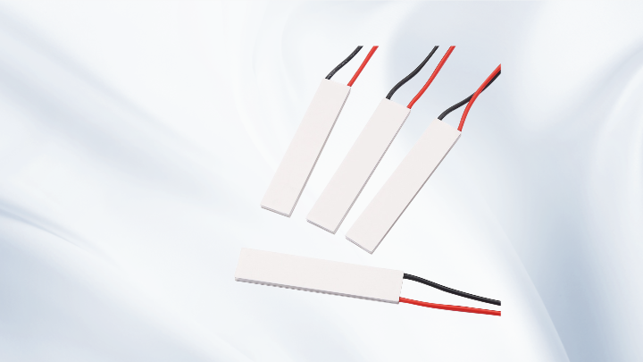
Thermoelectric Cooler Top 10 Selection Criteria Every Engineer Should Know
Why a Structured Selection Process Matters
A thermoelectric cooler is a heat pump, not a refrigerator. It moves heat from a cold side to a hot side, and it adds its own electrical power to that heat flow. That single principle explains why so many TEC designs fail after prototyping: the module was selected on cooling capacity alone, while the hot side was never given a realistic path to dissipate the combined heat load. Working through the Thermoelectric Cooler Top 10 criteria in order forces you to confront that reality before you commit to a bill of materials.
The ten criteria below are not ranked by importance, because their importance changes with the application. A miniature TEC for an optical sensor has different priorities than a multi-stage TEC for a laboratory instrument. What stays constant is the relationship between them.
The Thermoelectric Cooler Top 10 Criteria in Engineering Terms
1. Heat Load (Qc)
Start with the total heat that must be pumped away from the cold side. This includes the active load (a laser diode, a sensor, an electronic component), plus passive parasitic gains through insulation, mounting hardware, and air convection. Engineers routinely underestimate parasitics. If the passive gain is larger than the active load, the TEC is fighting a losing battle regardless of its rated capacity.
2. Required Temperature Difference (ΔT)
ΔT is the difference between the cold-side and hot-side temperatures, not between the cold side and ambient. This distinction is critical. A target of 5 °C on the cold side in a 25 °C room assumes a 25 °C hot side, which is only true with an excellent heatsink. In practice the hot side may run 15–20 °C above ambient, so the real ΔT is much larger than the design brief suggests.
3. Qmax — Maximum Cooling Capacity
Qmax is the heat pumping rate at a specific reference condition, typically with the cold side and hot side at the same temperature and the module driven at Imax. It defines the upper boundary of the module, not its working point. A common mistake is selecting a TEC where the required heat load is close to Qmax. In that region the achievable ΔT collapses toward zero, and the design has no margin.
4. ΔTmax — Maximum Temperature Difference
ΔTmax is achieved at zero heat load. It represents the point where the Peltier effect is exactly balanced by thermal conduction and Joule heating back through the module. Qmax and ΔTmax therefore cannot be reached at the same operating condition. Any datasheet that implies otherwise is being misread. Practical designs typically operate somewhere between 40 % and 70 % of ΔTmax, depending on how much heat must be moved.
5. Imax and Vmax
Imax is the current at which Qmax and ΔTmax are specified, and Vmax is the corresponding voltage at that current and at the reference hot-side temperature. These values define the module's electrical envelope, not a recommended drive point. Driving a TEC above Imax increases Joule heating faster than it increases cooling, which reduces net performance and shortens service life. In most systems the module is driven below Imax to improve efficiency and reduce self-heating.
6. Hot-Side Temperature and Ambient Conditions
Every TEC parameter shifts with hot-side temperature. A hotter hot side lowers ΔTmax and reduces Qmax, because heat conduction back through the module increases. This is why enclosure design, airflow, and ambient conditions belong in the selection process from day one, not as an afterthought during thermal validation.
7. Heat Dissipation and Heatsink Thermal Resistance
The heat rejected at the hot side equals the cold-side heat load plus the electrical input power. That total must pass through the heatsink, the thermal interface material, and the mounting interface. Heatsink thermal resistance sets how much the hot side rises above ambient for a given wattage. If the required hot-side temperature cannot be maintained, the cold side will never reach its target, no matter how capable the module is.
8. Thermal Interface Material and Mounting
Thermal grease, pads, and phase-change materials all behave differently under compression and thermal cycling. Contact pressure matters as much as the material. Uneven clamping creates local hot spots and mechanical stress on the ceramic substrates, which is one of the more common causes of premature TEC failure in fielded equipment.
9. Power Consumption and Efficiency
A TEC is a low-efficiency device by nature. The coefficient of performance falls sharply as ΔT increases. For battery-powered or thermally constrained systems, this makes the drive point a design decision rather than a detail. Reducing current slightly often improves net cooling while lowering total power draw, because self-heating drops.
10. Form Factor, Stages, and Environment
Finally, match the mechanical and environmental requirements: footprint and height limits, whether a miniature TEC is needed for a compact optical package, whether a multi-stage TEC is required for a large ΔT at low heat load, and whether the operating environment demands a high-temperature TEC with suitable solder and ceramic construction. For non-standard geometries, a custom TEC may be more practical than compromising the thermal design around an off-the-shelf size.
How These Parameters Interact in Real Designs
Consider a small enclosed instrument that must hold a sensor at 10 °C in a 30 °C ambient. The engineer first estimates the sensor's dissipation and parasitic gains — say a few watts total. The hot side must sit near 45 °C given a modest heatsink, so the required ΔT is 35 K. If the candidate module's ΔTmax is 68 K, the design is operating at roughly half of maximum, which is a reasonable working region. If the calculated ΔT lands above 80 % of ΔTmax, the design will likely need a larger module, a better heatsink, or a multi-stage approach.
Notice how the sequence works: heat load and ΔT define the requirement, Qmax and ΔTmax define the module envelope, and thermal resistance decides whether the envelope is actually usable.
Frequently Asked Questions
Can a TEC reach both Qmax and ΔTmax at the same time?
No. Qmax is specified at zero temperature difference, while ΔTmax is specified at zero heat load. They are two endpoints of the same performance curve. A real operating point always sits between them, and its location depends on heat load, hot-side temperature, and drive current.
Why does my Peltier cooler stop cooling when I increase the current?
Beyond a certain point, additional current produces more Joule heating inside the module than additional Peltier cooling. The net cooling rate falls, and the cold side can actually warm up. This is a strong indication that the module is being driven past its useful operating range or that the hot side cannot reject the added heat.
Is a larger module always better?
Not necessarily. A larger module moves more heat but also draws more power and requires a proportionally larger heatsink. If the heatsink is unchanged, a bigger TEC can make the hot side hotter and the cold side warmer than before.
When should I consider a multi-stage TEC?
Multi-stage modules are useful when a large temperature difference is needed at a relatively small heat load, such as in detector or sensor cooling. They are less suitable for high heat loads, because each stage adds its own electrical power to the heat that must be rejected.
Conclusion
The Thermoelectric Cooler Top 10 criteria are really one connected system: heat load and ΔT define the requirement, Qmax, ΔTmax, Imax, and Vmax describe the module envelope, and heat dissipation, thermal interfaces, power budget, and form factor determine whether that envelope can be realized in hardware. Selecting a TEC without that full picture usually leads to a design that works on paper and drifts in the field. Taking the time to evaluate each criterion against real operating conditions — and choosing a supplier who can support the thermal design rather than just quote a part number — is what turns a thermoelectric cooling concept into a reliable product.
Meta Information
META TITLE: Thermoelectric Cooler Top 10 Selection Criteria for Engineers
META DESCRIPTION: Learn the Thermoelectric Cooler Top 10 selection criteria — heat load, Qmax, ΔTmax, Imax, heatsink design, and power — to specify a reliable TEC.