


Using a Thermoelectric Cooler Recommended Ranking Chart for Smarter TEC Selection
Using a Thermoelectric Cooler Recommended Ranking Chart for Smarter TEC Selection
What Is a Thermoelectric Cooler Recommended Ranking Chart?
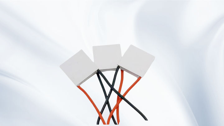
A Thermoelectric Cooler Recommended Ranking Chart is not a product ranking in the traditional sense. Instead, it is a comparative tool that helps engineers evaluate and prioritize TEC modules based on their performance characteristics under various operating conditions. Unlike a simple list of “best” products, this chart organizes thermoelectric coolers by key specifications such as Qmax, ΔTmax, Imax, and Vmax, along with thermal and electrical resistances. Its purpose is to guide selection by matching the TEC’s capabilities to the actual heat load, temperature difference, and thermal environment of the application.
In practice, a Thermoelectric Cooler Recommended Ranking Chart serves as a decision matrix. It allows you to quickly narrow down suitable Peltier modules by comparing how different TECs perform at your specific hot-side and cold-side temperatures. Because TEC performance is highly dependent on operating conditions, a chart that only lists maximum ratings can be misleading. A well-constructed chart includes performance curves or tables that show cooling capacity (Qc) at various temperature differences (ΔT) and input currents.
Key Parameters in a Thermoelectric Cooler Recommended Ranking Chart
To use the chart effectively, you must understand the parameters it presents and how they interrelate.
Qmax and ΔTmax: The Fundamental Trade-off
Qmax is the maximum cooling capacity a TEC can achieve when the temperature difference (ΔT) between the hot and cold sides is zero. ΔTmax is the maximum temperature difference a TEC can produce when the heat load (Qc) is zero. These two parameters are often listed together, but they cannot be achieved simultaneously. In real applications, the TEC operates somewhere between these extremes. As ΔT increases, the achievable Qc decreases. Therefore, a TEC with a high Qmax may not deliver the required cooling if your application demands a large ΔT. The chart helps you find the right balance.
Imax and Vmax
Imax is the input current at which Qmax is achieved for a given hot-side temperature. Vmax is the corresponding voltage at that current. These values define the electrical operating point for maximum cooling. However, running a TEC at Imax is not always practical because it leads to high power consumption and significant Joule heating. Most designs operate at a fraction of Imax to optimize efficiency and reliability. The chart typically includes Imax and Vmax so you can estimate the electrical requirements and select an appropriate power supply.
Electrical Resistance and Thermal Conductance
Other parameters in the chart may include AC resistance and thermal conductance. AC resistance affects the TEC’s efficiency and power loss, while thermal conductance influences how heat flows through the module. These values help predict performance at non-optimal conditions.
How to Use a Thermoelectric Cooler Recommended Ranking Chart for Your Application
Using the chart effectively requires a systematic approach. Follow these steps:
1. Define your heat load (Qc). Determine the amount of heat that must be pumped from the cold side. This includes the active load plus any parasitic heat gains.
2. Determine the required temperature difference (ΔT). This is the difference between the cold-side setpoint and the expected hot-side temperature. Remember that the hot-side temperature depends on your heatsink and ambient conditions.
3. Estimate the hot-side temperature (Th). TEC performance is strongly influenced by Th. A lower Th allows for greater cooling capacity and higher efficiency. The chart should provide data at various Th values.
4. Find TECs that meet your Qc at your ΔT and Th. Use the performance curves or tables in the chart to identify modules that can deliver the required Qc. Pay attention to the input current and voltage at that operating point.
5. Compare candidates. Evaluate the shortlisted TECs based on power consumption, size, cost, and availability. The chart helps you see which module offers the best fit without over-specifying.
Heat Dissipation and Thermal Management Considerations
A common mistake is to focus solely on the TEC’s cold-side performance while neglecting heat dissipation on the hot side. The hot side of a Peltier cooler must reject both the pumped heat (Qc) and the electrical power (Pin). The total heat to be dissipated is Qh = Qc + Pin. If the heatsink cannot handle this load, the hot-side temperature will rise, increasing ΔT and reducing the TEC’s cooling capacity. In extreme cases, the TEC may fail to cool at all.
When using a Thermoelectric Cooler Recommended Ranking Chart, always consider the thermal resistance of your heatsink, the interface material between the TEC and the heatsink, and the ambient conditions. A TEC that looks promising on paper may underperform if the hot side is not managed properly. Forced-air convection, liquid cooling, or heat pipes may be necessary depending on the power density.
Common Pitfalls When Using a Thermoelectric Cooler Recommended Ranking Chart
Even experienced engineers can make mistakes when interpreting TEC data. Here are some pitfalls to avoid:
Assuming Qmax and ΔTmax are simultaneous. As explained, these are极限 values that cannot be reached at the same time. Always use performance curves for your actual operating conditions.
Ignoring hot-side temperature. A TEC’s capacity drops significantly as Th rises. Ensure your chart data reflects realistic Th values.
Under-sizing the heatsink. The hot side is often the bottleneck. A poor heatsink will negate the benefits of a high-performance TEC.
Overlooking thermal interface materials. Even a small thermal resistance at the interface can reduce performance. Use high-quality thermal paste or pads.
Operating at Imax continuously. While Imax gives maximum cooling, it also generates maximum heat and stress. Most applications benefit from operating at 50–70% of Imax.
Frequently Asked Questions
Can I use a Thermoelectric Cooler Recommended Ranking Chart to pick a TEC for both heating and cooling?
Yes, TECs can heat and cool by reversing the current direction. However, the performance parameters (Qmax, ΔTmax) apply to cooling mode. In heating mode, the TEC acts as a heat pump, and the heating capacity is typically higher. The chart’s data still helps you understand the module’s capabilities, but you must consider the reversed polarity and heat flow.
What is the difference between Qmax and the actual cooling capacity I will get?
Qmax is the maximum cooling capacity at zero temperature difference. In real applications, you always have a ΔT, so the actual cooling capacity (Qc) is lower than Qmax. The higher the ΔT, the lower the Qc. Use the performance curves in the chart to find Qc at your specific ΔT and hot-side temperature.
How do I choose between a single-stage and multi-stage TEC?
Single-stage TECs are suitable for ΔT up to about 70°C. If you need larger temperature differences (e.g., for CCD cooling or scientific instruments), multi-stage TECs can achieve ΔT of 100°C or more. However, multi-stage modules have lower cooling capacity and higher power consumption. The chart should indicate the number of stages and the achievable ΔT range.
Why does my TEC not reach the expected ΔT?
Common causes include insufficient heatsink capacity, high thermal resistance at interfaces, heat leakage through mounting screws or air gaps, and operating at a lower current than specified. Also, the heat load may be higher than estimated. Review your thermal design and compare actual hot-side temperature with assumptions.
Can I run a TEC at a higher voltage than Vmax?
No. Exceeding Vmax or Imax can damage the module due to excessive current and heat. Always operate within the specified limits. If you need more cooling, consider a larger TEC or improve heat dissipation.
Meta Information
META TITLE: Thermoelectric Cooler Recommended Ranking Chart: TEC Selection Guide
META DESCRIPTION: Learn how to use a Thermoelectric Cooler Recommended Ranking Chart to select the right TEC module. Understand Qmax, ΔTmax, heat dissipation, and key selection criteria.
Conclusion
A Thermoelectric Cooler Recommended Ranking Chart is a valuable engineering tool that helps you navigate the complex trade-offs in Peltier cooler selection. By understanding parameters like Qmax, ΔTmax, Imax, and Vmax, and by considering heat load, hot-side temperature, and thermal management, you can choose a TEC that meets your application’s requirements without over-specifying or under-performing. Remember that actual performance depends on real operating conditions, so always use performance curves and validate your design with prototype testing. KKG offers a range of TEC modules—including single-stage, multi-stage, and high-temperature types—and our application engineers can help you interpret selection data for your specific project. Proper TEC selection leads to reliable, efficient thermoelectric cooling systems.