


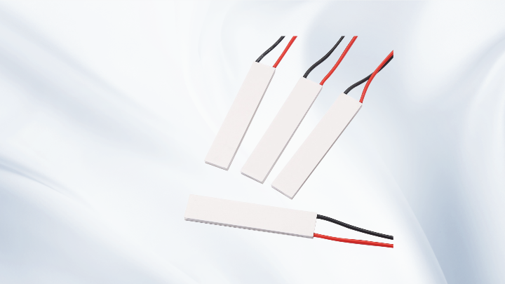
Which Is the Strongest Thermoelectric Cooler? A Practical Guide to TEC Selection
Which Is the Strongest Thermoelectric Cooler? A Practical Guide to TEC Selection
Engineers and product designers often search for which is the strongest thermoelectric cooler expecting a single part number to appear. In practice, thermoelectric cooling does not work that way. A TEC module is not "strong" in isolation; it is strong only relative to a specific heat load, a required temperature difference, a hot-side condition, and a heat sink that can remove the waste heat. Two modules can look identical on a datasheet and behave completely differently once installed. This article explains what actually determines cooling power in a Peltier cooler and how to choose the right module for your design instead of chasing a number that has no meaning outside its operating conditions.
What "Strongest" Really Means in Thermoelectric Cooling
When people ask which is the strongest thermoelectric cooler, they usually mean one of three different things: the module that pumps the most heat, the module that reaches the largest temperature difference, or the module that holds a cold surface at a target temperature in a real enclosure. These are not the same requirement, and the modules that satisfy them are not the same either.
A module with a very large Qmax pumps a lot of heat but typically cannot reach an extreme temperature difference. A multi-stage module can reach a large ΔT but moves very little heat. A module that performs well in a small, well-insulated enclosure may be a poor choice for an open system with a large ambient load. The correct question is therefore not "which module is strongest," but "which module is strongest for this thermal problem."
Qmax, ΔTmax, Imax, and Vmax: The Four Numbers That Define a TEC Module
Every thermoelectric cooler datasheet is built around four reference parameters. Understanding them, and understanding their limits, is the foundation of any correct selection.
Qmax — Maximum Cooling Capacity
Qmax is the maximum heat the module can pump at a temperature difference of zero. In other words, the cold side and hot side are at the same temperature, and the module is moving as much heat as it physically can. This is a theoretical reference point, not a working condition. As soon as the cold side becomes colder than the hot side, the achievable cooling capacity drops.
ΔTmax — Maximum Temperature Difference
ΔTmax is the largest temperature difference the module can create between its hot side and cold side, and it is reached only when the heat load is essentially zero. It is measured under a defined hot-side temperature, because ΔTmax changes with hot-side conditions. A module rated for a large ΔTmax cannot simultaneously deliver Qmax; the two points sit at opposite ends of the same performance curve.
Imax and Vmax — Electrical Limits
Imax is the current at which Qmax and ΔTmax are specified, and Vmax is the corresponding voltage across the module at that current and at the reference hot-side temperature. These are not recommended continuous operating points for every design. Many practical systems run below Imax to improve efficiency and reduce thermal stress, accepting a lower cooling capacity in exchange for lower power consumption and better long-term reliability.
The important engineering relationship is this: Qmax and ΔTmax cannot normally be achieved at the same time under the same operating conditions. Any claim that a module delivers both simultaneously should be treated as a misunderstanding of the datasheet.
Which Is the Strongest Thermoelectric Cooler Depends on Heat Load and Target ΔT
The practical selection process starts from the application, not from the module. Before comparing any TEC, define the following:
1. Total heat load. This includes the active load (electronics, laser diode, sensor, sample) plus any passive heat leaking in through insulation, wiring, and mounting hardware. Passive leaks are frequently underestimated and can exceed the active load in small enclosures.
2. Required cold-side temperature. Stated as an absolute target, not just a delta.
3. Realistic hot-side temperature. This is set by ambient conditions, the heat sink, and the fan or liquid cooling available. It is often the single most important variable in the whole design.
4. Available power budget and space. A module that requires more current than the supply can deliver, or is larger than the mounting area allows, is not a candidate regardless of its ratings.
Once these four items are known, the required ΔT is simply the hot-side temperature minus the target cold-side temperature. A module whose ΔTmax is only marginally above that required ΔT will deliver very little usable cooling capacity, because the performance curve falls steeply as ΔT approaches ΔTmax. A more capable choice is usually one with a comfortable ΔT margin, which may mean a different module architecture rather than a bigger single-stage part.
Single-Stage vs. Multi-Stage: Where Large Temperature Differences Come From
For most cooling applications, a single-stage Peltier module is the right answer. Single-stage modules offer the highest cooling capacity per unit of input power and are the standard choice for electronics cooling, sample holders, portable coolers, and temperature-stabilized optical components.
When the required ΔT exceeds what a single stage can reasonably deliver, a multi-stage TEC (cascaded) module becomes necessary. Each stage stacks on the previous one, so the temperature differences add up. The trade-off is significant: multi-stage modules move much less heat, consume more power per watt of cooling, and require careful control of the hot side. They are appropriate for detector cooling, scientific instrumentation, and other applications where a large ΔT matters more than raw capacity.
For compact designs, miniature TEC modules allow localized cooling of small components without disturbing the surrounding thermal environment. For high ambient conditions, high-temperature TEC modules built with suitable solder and ceramic materials maintain reliability where standard modules would degrade. When standard footprints, voltages, or mounting geometries do not fit, a custom TEC assembly can be designed around the mechanical and electrical constraints of the product.
Heat Dissipation: The Real Limit on Cooling Capacity
The most common reason a thermoelectric cooling system underperforms is not the module — it is the hot side. A TEC moves heat; it does not destroy it. The heat removed from the cold side, plus the electrical power delivered to the module, must be rejected to ambient through the heat sink.
If the heat sink cannot reject that total, the hot side rises, the achievable ΔT shrinks, and the cooling capacity collapses. This is why thermal resistance of the heat sink, the quality of the thermal interface material, mounting pressure, and airflow all directly affect the cold-side temperature. Improving the heat sink often produces a larger performance gain than switching to a higher-rated module.
Key design checks include: verifying that the heat sink thermal resistance is low enough at the expected airflow, ensuring even mounting pressure across the module, keeping the module flat and free of mechanical stress, and confirming that the hot-side temperature stays within the module's rated range under worst-case ambient conditions.
A Practical Selection Workflow
Step 1 — Estimate the heat load including passive losses, with a safety margin. Step 2 — Define the required ΔT from target cold-side temperature and realistic hot-side temperature. Step 3 — Shortlist modules whose ΔTmax gives a healthy margin above the required ΔT at the expected hot-side temperature. Step 4 — Compare cooling capacity at the actual operating point, not at Qmax. Datasheet curves or manufacturer selection software are needed here. Step 5 — Check electrical feasibility against the available supply: current, voltage, and total power consumption. Step 6 — Design the hot side first, then confirm the cold side with a thermal test. Step 7 — Validate under worst-case ambient, because performance at 25 °C ambient rarely predicts behavior at 50 °C.
Common Mistakes and Troubleshooting Tips
If a system cools poorly, check these points before replacing the module. Reversed polarity will heat instead of cool. Insufficient heat sink capacity causes the hot side to climb and the cold side to stall. Poor thermal interface contact — too little paste, uneven pressure, or a warped surface — adds thermal resistance exactly where it hurts most. Excessive current increases Joule heating inside the module and can reduce net cooling. Condensation on the cold side can short electronics and should be managed with sealing, conformal coating, or controlled dew point.
Frequently Asked Questions
Which is the strongest thermoelectric cooler for a given application?
The strongest module is the one whose ΔTmax and cooling capacity curve match your actual heat load, required temperature difference, and hot-side conditions. There is no universal answer; selection must be based on the operating point, not on a headline rating.
Can a TEC achieve Qmax and ΔTmax at the same time?
No. Qmax occurs at zero temperature difference, and ΔTmax occurs at zero heat load. They are the two endpoints of the same performance curve. Real operation always falls somewhere between them.
Does a higher current always mean more cooling?
Only up to a point. Increasing current raises both the pumped heat and the internal Joule heating. Beyond the optimum, additional current adds more heat than it removes, and efficiency drops sharply.
Why does my Peltier cooler perform worse in summer?
Higher ambient temperature raises the hot-side temperature, which reduces the achievable temperature difference. This is normal behavior and is why hot-side thermal design must be evaluated at worst-case ambient conditions.
When should I choose a multi-stage TEC instead of a single-stage module?
Choose multi-stage only when the required ΔT exceeds what a single stage can deliver at your heat load. If capacity is the limiting factor rather than temperature difference, a larger single-stage module is usually the better choice.
Conclusion
There is no single answer to which is the strongest thermoelectric cooler, because strength in thermoelectric cooling is defined by the application rather than the datasheet headline. Qmax, ΔTmax, Imax, and Vmax are reference points, not simultaneous operating targets, and the real performance of any Peltier module depends on heat load, hot-side temperature, input voltage and current, heat sink thermal resistance, interface quality, and installation conditions. Selecting or designing a suitable TEC solution therefore means starting from the thermal problem, defining the required ΔT and heat load, designing the hot side properly, and then choosing the module architecture — single-stage, multi-stage, miniature, high-temperature, or fully custom — that fits those constraints. That approach delivers reliable cooling far more consistently than looking for the largest number on a specification sheet.
META TITLE: Which Is the Strongest Thermoelectric Cooler? TEC Guide
META DESCRIPTION: Learn which is the strongest thermoelectric cooler for your design by comparing Qmax, ΔTmax, Imax, Vmax, heat load, and heat dissipation in real systems.