




Working With a Thermoelectric Cooler Manufacturer: A Practical TEC Selection Guide
Working With a Thermoelectric Cooler Manufacturer: A Practical TEC Selection Guide
Most thermoelectric cooling projects fail for the same reason: the module was chosen before the thermal problem was understood. A thermoelectric cooler manufacturer can supply curves, samples, and custom builds, but no datasheet can compensate for an undersized heatsink or an unmeasured heat load. This guide walks through the selection sequence that experienced TEC application engineers actually use — define the load, read the curves correctly, size the electrical interface, and solve heat dissipation first.
What a Thermoelectric Cooler Manufacturer Actually Provides
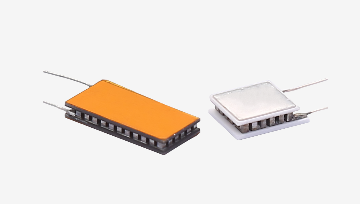
A TEC module, also called a Peltier module or Peltier cooler, is a solid-state heat pump. Current through the module moves heat from the cold side to the hot side. There are no compressors, no refrigerant, no moving parts, and the direction of heat flow reverses when polarity reverses. That makes thermoelectric cooling attractive for precise temperature control, compact instruments, and applications where vibration or maintenance access is a problem.
What separates a capable supplier from a catalog reseller is what happens after the standard part is ruled out. Custom ceramic footprints, non-standard heights, sealed or coated assemblies, miniature modules for tight optical packages, high-temperature constructions, and multi-stage stacks are all normal engineering requests. The important point is that these variations change the thermal and electrical behavior of the device, so they must be evaluated together with the application, not selected afterward.
The datasheet is a map, not a promise
Published parameters such as Qmax, ΔTmax, Imax, and Vmax are measured under defined reference conditions — typically a fixed hot-side temperature, near-vacuum insulation, and an idealized heat sink. Your assembly will not reproduce those conditions. Treat the datasheet as a boundary description of the module, and expect real cooling capacity to be lower than the headline number.
Step 1: Define the Heat Load Before Choosing a Module
The heat load is the total thermal energy the cold side must remove to hold a target temperature. It has two parts:
Active load — power dissipated by the device being cooled. A laser diode, sensor, CCD, or electronic component converts electrical energy into heat, and in many cases nearly all of it becomes heat.
Passive load — heat leaking into the cold side from the environment. This includes conduction through mounting hardware, wiring, and insulation, plus radiation and any convective path in a non-sealed enclosure. Passive load is often underestimated, and in small sensor systems it can dominate.
If the heat load is not quantified, module selection becomes guesswork. The achievable temperature difference between the cold side and hot side falls as heat load rises; a module that reaches a deep ΔT at zero load will reach a much smaller ΔT once a real load is attached.
An illustrative scenario
Suppose a sensor must be held at a fixed temperature, and the measured total heat load is 10 W. That number — not a guess — is the starting point. From there, the engineer decides the required cold-side temperature, estimates the hot-side temperature that the heat sink can realistically maintain at the given ambient, and derives the required ΔT. Only then does a module curve become meaningful.
Step 2: Interpret Qmax, ΔTmax, Imax, and Vmax Correctly
These four parameters describe the edges of the operating envelope, and they are frequently misread:
Qmax is the maximum heat pumping capacity, and it occurs at zero temperature difference — the cold side and hot side at the same temperature. It is not the cooling capacity you will get in a real application.
ΔTmax is the maximum temperature difference the module can produce, and it occurs at zero heat load — nothing attached to the cold side. It is not the temperature difference you will get while cooling something.
Imax and Vmax are the current and voltage at which Qmax is defined. They belong to that specific operating point.
The critical rule: Qmax and ΔTmax cannot be achieved simultaneously under the same operating condition. Every real application sits somewhere between the two extremes, on a curve whose shape depends on hot-side temperature, input current, and module construction. Pushing current beyond Imax increases Joule heating faster than it increases heat pumping, so cooling performance degrades rather than improves.
How to read a performance curve
Manufacturers publish cooling capacity versus ΔT curves, each drawn at a fixed hot-side temperature and a fixed input current or voltage. To use them: fix the hot-side temperature your thermal design can hold, choose the ΔT your application requires, then read the available cooling capacity at the cold side. Compare that value with your heat load. If capacity does not exceed the load with reasonable margin, change the module, the hot-side temperature, or the heat load — not the graph.
Step 3: Match Voltage, Current, and Power Supply to the Application
Electrical selection follows thermal selection. Once an operating point is chosen, the module's electrical resistance at that point determines the voltage needed for the desired current — or the current needed for the available voltage. In practice, engineers usually pick the current, because it drives both cooling and losses.
Practical considerations:
Power supply headroom. A supply that cannot deliver the required current will simply operate the module at a lower, unplanned point on the curve.
Ripple and noise. Significant AC ripple creates additional resistive heating without useful heat pumping. For precision temperature control, a low-ripple linear drive is often preferable to unfiltered switching drive.
PWM control. Pulse-width modulation is common and efficient, but the switching frequency and the thermal mass of the load determine how much temperature ripple appears at the cold side.
Power consumption and COP. Efficiency falls as ΔT grows. Deep cooling of a small load can consume far more electrical power than the load itself, and that power becomes additional heat that must be removed from the hot side.
Step 4: Heat Dissipation Is Half the Design
The hot side must reject both the pumped heat and the electrical power consumed: Qh = Qc + Pin. This is why an undersized heat sink is the most common cause of disappointing TEC performance.
Hot-side temperature rise is governed by thermal resistance: the heat sink, the thermal interface material, the mounting interface, and the module's own ceramic and metallization layers all contribute. The chain behaves like a series of resistances, and the largest one dominates.
Several practical points follow from this:
Every degree of hot-side temperature reduces the ΔT available at the cold side. Improving the heat sink or the airflow is often more effective than changing the module.
Thermal interface material matters. An uneven or excessively thick bond line adds resistance and creates hot spots across the module footprint.
Mounting pressure and flatness must be controlled. Over-torquing cracks ceramics; under-torquing leaves voids. Both degrade performance and reliability.
Ambient temperature sets the floor for the entire system. A design validated on a bench at room temperature may not hold its cold-side setpoint inside a warm enclosure.
Step 5: When to Move to a Custom or Multi-Stage Solution
Standard single-stage modules cover a wide range of applications, but three situations call for a different approach:
Large ΔT requirements. When the needed temperature difference exceeds what a single stage can deliver at the required heat load, multi-stage TEC assemblies stack modules so each stage handles a progressively smaller heat load. Staging raises achievable ΔT at the cost of efficiency and complexity.
Space-constrained packages. Miniature TEC modules are used in optoelectronics, sensors, and handheld instruments where footprint and height are fixed constraints.
Harsh environments. High-temperature TEC constructions and sealed assemblies address applications with elevated ambient conditions, thermal cycling, or moisture exposure.
In these cases, an experienced thermoelectric cooler manufacturer can adjust geometry, pellet count, ceramic type, sealing, and lead configuration to fit the mechanical envelope while keeping the thermal design coherent. Bringing the supplier into the design discussion early — with heat load, target temperatures, ambient conditions, and available space — is far more productive than requesting a quote for an underspecified part.
Frequently Asked Questions
Can my TEC reach ΔTmax in a real application?
No. ΔTmax is defined at zero heat load and under reference conditions. As soon as a real load is attached and the hot side warms above the reference temperature, the achievable ΔT drops. Design for a ΔT well below the datasheet maximum and verify it under your actual thermal stack.
How do I estimate the cooling capacity I need?
Measure or calculate the active heat load, add the passive load from conduction, radiation, and convection into the cold side, then apply margin for thermal interface losses and operating variation. The total is the minimum cooling capacity the module must deliver at your target ΔT — not at ΔT equals zero.
Why is my Peltier cooler not reaching the target temperature?
The usual causes, in order of frequency: an undersized or poorly mounted heat sink, excessive hot-side temperature rise, an underestimated heat load, insufficient thermal interface material performance, or a power supply that cannot deliver the current required for the intended operating point. Check hot-side temperature first — it explains most shortfalls.
When should I consider a multi-stage TEC?
When a single-stage module cannot provide the required ΔT at the required heat load, even with an optimized heat sink. Multi-stage assemblies are also used when the load is very small but the target temperature is far below ambient. They cost more, consume more power, and demand tighter mechanical tolerances.
What information should I provide when requesting a TEC design?
Heat load, target cold-side temperature, expected hot-side temperature or ambient, available footprint and height, input voltage or current limits, duty cycle, environmental conditions, and mechanical mounting constraints. With those inputs, a supplier can narrow the module family quickly instead of exchanging several rounds of samples.
Conclusion
Thermoelectric cooling is a system problem. The module is one element in a chain that includes the heat load, the thermal interface, the heat sink, the power supply, and the ambient environment. The sequence that works is consistent: quantify the heat load, choose an operating point below the datasheet extremes, confirm that the electrical interface can deliver the required current, and design the hot side so it never becomes the limiting factor.
Working with an experienced thermoelectric cooler manufacturer shortens this process because the supplier can read the same thermal problem you do and respond with module geometry, staging, or sealing that fits the application. Whether the requirement is a miniature module for a sensor package, a multi-stage stack for a deep temperature difference, or a high-temperature construction for a demanding environment, the value comes from matching the module to the thermal design — not from the headline parameters on the first page of the datasheet.
META TITLE: Thermoelectric Cooler Manufacturer: TEC Selection Guide
META DESCRIPTION: Learn how to select a TEC module from a thermoelectric cooler manufacturer. Understand Qmax, ΔTmax, heat load, heat dissipation, and thermal management in practice.
